Difference between revisions of "JD"
From wiki.pengtools.com
(→Math & Physics) |
(→Math & Physics) |
||
| Line 20: | Line 20: | ||
<td>Steady state</td> | <td>Steady state</td> | ||
<td><math> {J_D} = \frac{1}{ln{\frac{r_e}{r_w}-\frac{1}{2}+S}} </math></td> | <td><math> {J_D} = \frac{1}{ln{\frac{r_e}{r_w}-\frac{1}{2}+S}} </math></td> | ||
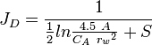
| − | <td> {J_D} = \frac{1}{\frac{1}{2}ln{\frac{4.5\ A}{C_A\ {r_w}^2}+S}}</td> | + | <td><math>{J_D} = \frac{1}{\frac{1}{2}ln{\frac{4.5\ A}{C_A\ {r_w}^2}+S}}</math></td> |
</tr> | </tr> | ||
Revision as of 11:40, 11 July 2023
Contents
Brief
JD - dimensionless productivity index[1], inverse of dimensionless pressure (based on average pressure) which contains the type of flow regime, boundary condition, drainage shape and stimulation [2].
Math & Physics

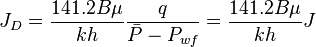
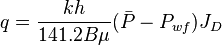
From the Darcy's law for the unfractured well the JD is:
| Well in circular drainage area | Well in a drainage area with the shape factor  |
|
|---|---|---|
| Steady state | 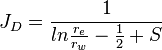 |
 |
| Pseudo steady state | 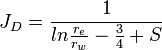 |
-- |
Oil
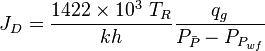
Gas
Maximum 
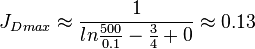
The undamaged unstimulated vertical well potential in a pseudo steady radial flow is:
The maximum possible stimulated well potential for pseudo steady linear flow is:
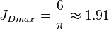 , see 6/π stimulated well potential
The maximum possible stimulated well potential for steady state linear flow is:
 , see 4/π stimulated well potential
Nomenclature
 = formation volume factor, bbl/stb
 = productivity index, stb/psia
- = dimensionless productivity index, dimensionless
 = permeability times thickness, md*ft
 = average reservoir pressure, psia
 = dimensionless pressure (based on average pressure), dimensionless
 = average reservoir pseudopressure, psia2/cP
 = well flowing pressure, psia
 = average well flowing pseudopressure, psia2/cP
 = flowing rate, stb/d
 = gas rate, MMscfd
 = wellbore radius, ft
 = drainage radius, ft
 = skin factor, dimensionless
 = temperature, °R
Greek symbols
 = viscosity, cp
See Also
References
- ↑ Rueda, J.I.; Mach, J.; Wolcott, D. (2004). "Pushing Fracturing Limits to Maximize Producibility in Turbidite Formations in Russia"
 (SPE-91760-MS). Society of Petroleum Engineers.
- ↑
Wolcott, Don (2009). Applied Waterflood Field Development
 . Houston: Energy Tribune Publishing Inc.