Difference between revisions of "JD"
From wiki.pengtools.com
(→Math & Physics) |
(→Math & Physics) |
||
| Line 21: | Line 21: | ||
<th>Well in circular drainage area</th> | <th>Well in circular drainage area</th> | ||
<th>Well in the drainage area with the shape factor <math> {C_A} </math></th> | <th>Well in the drainage area with the shape factor <math> {C_A} </math></th> | ||
| − | |||
</tr> | </tr> | ||
<tr> | <tr> | ||
| − | <td> | + | <td>Steady state</td> |
| − | <td> | + | <td><math> {J_D} = \frac{1}{ln{\frac{r_e}{r_w}-\frac{1}{2}+S}} </math></td> |
<td> Calculated with Nodal Analysis using the [[PQplot]] by setting the flowing wellhead pressure (FWHP) equal to the current flowing line pressure (FLP) at the well head. <BR>Use the current value of [[JD]].</td> | <td> Calculated with Nodal Analysis using the [[PQplot]] by setting the flowing wellhead pressure (FWHP) equal to the current flowing line pressure (FLP) at the well head. <BR>Use the current value of [[JD]].</td> | ||
| − | + | ||
</tr> | </tr> | ||
<tr> | <tr> | ||
| − | <td> | + | <td>Pseudo steady state</td> |
| − | <td> | + | <td><math> {J_D} = \frac{1}{ln{\frac{r_e}{r_w}-\frac{3}{4}+S}} </math></td> |
<td>Calculated the same way as for the '''Gas Flowing''' case</td> | <td>Calculated the same way as for the '''Gas Flowing''' case</td> | ||
| − | |||
| − | |||
| − | |||
| − | |||
| − | |||
| − | |||
| − | |||
| − | |||
</tr> | </tr> | ||
Revision as of 11:29, 11 July 2023
Contents
Brief
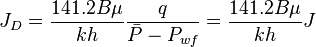
JD - dimensionless productivity index[1], inverse of dimensionless pressure (based on average pressure) which contains the type of flow regime, boundary condition, drainage shape and stimulation [2].
Math & Physics

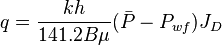
From the Darcy's law for an unfractured well located in the center of a circular drainage area, the JD is:
Pseudo-steady state:
Steady state:
 |
Well in circular drainage area | Well in the drainage area with the shape factor  |
|---|---|---|
| Steady state | 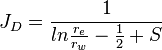 |
Calculated with Nodal Analysis using the PQplot by setting the flowing wellhead pressure (FWHP) equal to the current flowing line pressure (FLP) at the well head. Use the current value of JD. |
| Pseudo steady state | 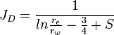 |
Calculated the same way as for the Gas Flowing case |
Oil
Gas
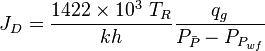
Maximum 
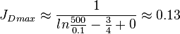
The undamaged unstimulated vertical well potential in a pseudo steady radial flow is:
The maximum possible stimulated well potential for pseudo steady linear flow is:
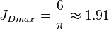 , see 6/π stimulated well potential
The maximum possible stimulated well potential for steady state linear flow is:
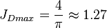 , see 4/π stimulated well potential
Nomenclature
 = formation volume factor, bbl/stb
 = productivity index, stb/psia
- = dimensionless productivity index, dimensionless
 = permeability times thickness, md*ft
 = average reservoir pressure, psia
 = dimensionless pressure (based on average pressure), dimensionless
 = average reservoir pseudopressure, psia2/cP
 = well flowing pressure, psia
 = average well flowing pseudopressure, psia2/cP
 = flowing rate, stb/d
 = gas rate, MMscfd
 = wellbore radius, ft
 = drainage radius, ft
 = skin factor, dimensionless
 = temperature, °R
Greek symbols
 = viscosity, cp
See Also
References
- ↑ Rueda, J.I.; Mach, J.; Wolcott, D. (2004). "Pushing Fracturing Limits to Maximize Producibility in Turbidite Formations in Russia"
 (SPE-91760-MS). Society of Petroleum Engineers.
- ↑ Cite error: Invalid
<ref>tag; no text was provided for refs namedDW