Difference between revisions of "3 Phase IPR"
From wiki.pengtools.com
(→Nomenclature) |
(→3 Phase IPR calculation example) |
||
| (4 intermediate revisions by the same user not shown) | |||
| Line 20: | Line 20: | ||
==[[3 Phase IPR]] calculation example== | ==[[3 Phase IPR]] calculation example== | ||
| − | |||
Following the well #1 example given by Brown<ref name=KermitBrown1984 />on Figure 5.8, page 191: | Following the well #1 example given by Brown<ref name=KermitBrown1984 />on Figure 5.8, page 191: | ||
| − | |||
| − | |||
| − | |||
| − | |||
| − | |||
| − | |||
| − | + | ''In progress ...'' | |
| − | |||
| − | |||
| − | |||
| − | |||
| − | |||
| − | |||
| − | |||
| − | |||
== Nomenclature == | == Nomenclature == | ||
| − | :<math> B</math> = volume factor, bbl/stb | + | :<math> B</math> = volume factor, bbl/stb oil; bbl/scf gas |
:<math> GLR</math> = gas liquid ratio, scf / bbl | :<math> GLR</math> = gas liquid ratio, scf / bbl | ||
:<math> q </math> = flowing rate, stb/d | :<math> q </math> = flowing rate, stb/d | ||
| Line 48: | Line 33: | ||
:<math> WCUT</math> = water cut, fraction | :<math> WCUT</math> = water cut, fraction | ||
===Subscripts=== | ===Subscripts=== | ||
| + | :g = gas<BR/> | ||
:o = oil<BR/> | :o = oil<BR/> | ||
:sc = standard conditions<BR/> | :sc = standard conditions<BR/> | ||
Latest revision as of 07:51, 17 April 2019
Contents
Three-phase Inflow Performance Relationship

3 Phase IPR Curve [1]
3 Phase IPR is an IPR curve calculated on the basis of total barrels of produced fluid, including gas.
3 Phase IPR curve is used in Pump Design software for pump sizing.
Math and Physics
The volume of 1 stb of liquid plus associated gas at any pressure and temperature is given by[1]:

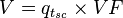
The total volume of produced fluid rate (liquid plus gas) at any conditions of pressure and temperature:
 is calculated as usual using:
- Vogel's IPR equation
- Composite IPR equation
3 Phase IPR calculation example
Following the well #1 example given by Brown[1]on Figure 5.8, page 191:
In progress ...
Nomenclature
 = volume factor, bbl/stb oil; bbl/scf gas
 = gas liquid ratio, scf / bbl
 = flowing rate, stb/d
  = solution gas ration, scf / stb
 = total volume of produced fluid rate (inducing gas), bbl/d
 = volume factor, bbl/stb
 = water cut, fraction
Subscripts
- g = gas
- o = oil
- sc = standard conditions
- t = total
- w = water