Difference between revisions of "Dranchuk correlation"
From wiki.pengtools.com
Gprotsykov (talk | contribs) |
|||
| Line 21: | Line 21: | ||
A11 = 0.7210 | A11 = 0.7210 | ||
:<math> z = 1+ | :<math> z = 1+ | ||
| − | (A_1 | + | \left(A_1 |
+\frac{A_2}{T_{pr}} | +\frac{A_2}{T_{pr}} | ||
+\frac{A_3}{T^3_{pr}} | +\frac{A_3}{T^3_{pr}} | ||
+\frac{A_4}{T^4_{pr}} | +\frac{A_4}{T^4_{pr}} | ||
+\frac{A_5}{T^5_{pr}} | +\frac{A_5}{T^5_{pr}} | ||
| − | )* \rho_r+ | + | \right)* \rho_r+ |
(A_6 | (A_6 | ||
+\frac{A_7}{T_{pr}} | +\frac{A_7}{T_{pr}} | ||
Revision as of 10:34, 25 April 2017
Brief
Liquid loading is a phenomenon when the gas phase does't provide sufficient transport energy to lift the liquids out of the well.
In 1969 Turner et al. published an empirical correlation defining the Liquid loading gas velocity.
Math & Physics
equation on gas compressibility factor z
   A1 = 0.3265
   A2 = –1.0700
   A3 = –0.5339
   A4 = 0.01569
   A5 = –0.05165
   A6 = 0.5475
   A7 = –0.7361
   A8 = 0.1844
   A9 = 0.1056
   A10 = 0.6134
   A11 = 0.7210

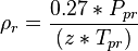
where


Discussion
To avoid the Liquid loading the gas velocity should be above the Liquid loading velocity.
The higher the gas rate the higher the gas velocity.
The lower the wellhead flowing pressure the higher the gas rate.
The bigger the tubing ID the higher the gas rate.
In case when the gas rate is limited by the Reservoir deliverability smaller tubing ID will increase the gas velocity.
Nomenclature
 = flow area, ft^2
 = flowing wellhead pressure, psia
 = gas rate, MMscf/d
 = gas density, lbm/ft3
 = liquid density, lbm/ft3
 = surface tension, dyne/cm (ref values: 60 - water, 20 - condensate) [1]
 = flowing temperature, °R
 = gas velocity, ft/sec
 = gas compressibility factor at flowing P & T, dimensionless
References
- ↑ 1.0 1.1 Turner, R. G.; Hubbard, A. E.; Dukler (Nov 1969). "Analysis and Prediction of Minimum Flow Rate for the Continuous Removal of Liquids from Gas Wells"
 . Journal of Petroleum Technology (SPE-2198-PA): 1475–1482.